ABUS EC700
ABUS EC700
| ABUS EC700 | |
 | |
| Name | ABUS EC700 |
|---|---|
| Manufacturer | ABUS |
| Lock Type | Cylinder |
| Lock Design | Pin-tumbler, Dimple |
| Specifications | |
| # of Components | 10 |
| Component Type | Pin-tumbler |
The Extra Classe 700, commonly referred to by its model number EC700, is a door cylinder lock made by ABUS. It is a dimple lock that uses the flat side of the key blade as a bitting area.
Principles of operation
The ABUS EC700 utilizes dimple keys but functions the same as a standard pin-tumbler lock. The key is bitted on both sides of the blade and is reversible. The lock uses ten chambers for pin-tumbler stacks. Four chambers in a row on the top of the lock and six chambers in a row on the bottom. Each of those chambers contains a set of key pin, driver, and spring. To open the lock, all ten pin-tumblers must be aligned at the shear line. (See also Pin-tumbler, Principles of operation)
ABUS utilizes a variety of security features to deter picking. At least two of the brass driver pins in the bottom row are spooled security pins. Standard pins have tapered edges to reduce feedback. The use of multiple rows of opposing pins in the EC700 adds another obstacle through a less-common implementation of this design. The four pins of the top row are directly opposite pins from the bottom row and touch in the middle when the key is not present. This configuration complicates picking because the force of the much stronger bottom springs oversets the pins of the top row. Picking attacks tend to rely on dedicated tools to work around this initial state. The Kale Kilit 164 BNE is another lock that shares this design feature.
Disassembly instructions
The use of a pinning shoe is the preferred method for disassembling a double euro cylinder. Another method is to use a segmented follower. The c-clips retaining both cores must first be removed and then both cores can be pulled out slightly in order to remove the center cam. One core should be rotated to approximately 4:30 or 7:30 o'clock position -- 135 degrees either clockwise or counter-clockwise -- once the cam is removed. This allows the core to be removed without driver pins entering gaps for the cam clutch. At that point, a segmented follower can be used to remove the core.
Locks not intended for installation and use can be disassembled in a quick but destructive procedure. The cylinder housing itself can be cut in the middle using a hacksaw or grinder. The cam will no longer be held in place and can be removed. The resulting two cut half euro cylinders can then be disassembled as outlined above.
Gallery
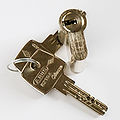
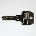
EC700 key
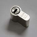
EC700 cut euro cylinder


