Chubb Mark IV Manifoil
Chubb Mark IV Manifoil
| Chubb Mark IV Manifoil | |
 | |
| Name | Chubb Mark IV Manifoil |
|---|---|
| Manufacturer | Chubb |
| Lock Type | Safe lock |
| Lock Design | Combination |
The Mark IV Manifoil is a combination safe lock made by Chubb. It is used in combination with the NATO Mersey for securing Ministry of Defense (MOD) safes in the United Kingdom. There is at least one publicly known manipulation method for the Mark IV, and the newest version, Mark VIII, has additional features for defeating it.
General
3 wheel high security lock that has – as the name suggests – features to foil manipulation. Despite having 3 wheels combination has 4 numbers and is dialed like a 4 wheel safe (5 right, 4 left etc) but the last number depends on lock orientation and is not changeable by the user. The forbidden zone also depends on this last number.
Last numbers per orientation
   RH – last number 0, forbidden zone 95 – 10
   VD – last number 25, forbidden zone 20 – 35
   LH – last number 50, forbidden zone 45 – 60
   VU – last number 75, forbidden zone 70 – 85
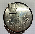
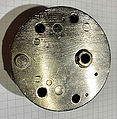
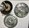
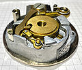
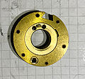
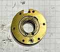
Lock with back cover on. Item code # 20 42 1726 from 1978. No R at the end of the serial number so the lock likely hasn't been refurbished. Change key hole is hidden under a spring-loaded cover on the upper left.
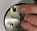
The change key hole cover.
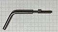
Change key.
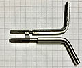
Change key compared to 3-wheel S&G change key.
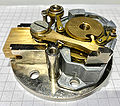
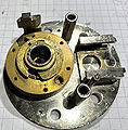
Bottom of lock, bolt on the left and unlocked. Note that the Manifoil / Mersey / Chatwood Milner footprint isn't compatible with Euro footprint / Magic Module without a conversion plate.


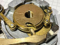
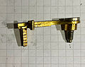
A: Bolt (unlocked).
B: Lever.
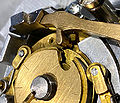
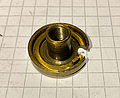
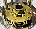
C: The eccentric (ie. off-center) primary cam. This is the drive cam that is directly attached to the spindle.
Eccentricity can be seen by looking at the edges of the middle part on the cam.
D: 2x friction rollers.
E: Zinc and lead shielding to prevent radiological attacks.
F: Change key hole in shielding.
More pictures of the lock can be found in the Disassembly section.
Manipulation resistance features
The Manifoil Mark IV has several features that are designed to make traditional manipulation methods hard or impossible. Zinc and lead are used at multiple points to provide protection against radiological attacks, and manipulation is hampered by splitting the cam in two and adding more friction in both the mechanism and the dial itself.
The split cam
Arguably the most important of these manipulation resistance features is the split cam, which is also the reason for the 4th number. The Mark IV has a two-part cam, with the drive cam (or the "primary cam" as it's also called) at the "top" directly attached to the spindle like usual, but underneath it there is a secondary cam which has a fly on it that is driven by a pin on the bottom of the primary cam – exactly the same way wheels work, in other words. This means that you can't control the secondary cam directly but have to go through a full rotation of the primary first. The primary cam is eccentric, meaning that it is not placed completely centrally on the spline and therefore sometimes sits closer to the nose and sometimes further in a way that makes it impossible to use either cam to get contact point readings off the wheel pack using usual methods.
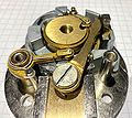
Cams and lever.
Secondary cam contact points.


When the primary cam is positioned where the contract area would be, the nose touches the secondary cam, meaning the primary can't be used for contact point readings as it's not even in contact with the lever.
When the secondary cam is positioned for taking readings, the nose rests on the primary cam and the fence isn't in contact with the wheel pack. While the secondary cam contact points can be felt, they don't measure the wheel pack so they're likely not useful.
This means that using the cam gates and lever nose to get information out of the lock directly is much, much harder. The nose does drag on the primary cam and this could be felt as increased friction and would give away information on how deep the nose has "sunk" if it wasn't for the next manipulation resistance feature.
Friction
Adding friction at a few different points masks what little information you could get out of the lock. One of these points is the dial.
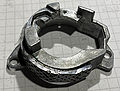
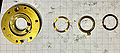
Dial in dial ring
Disassembled dial.
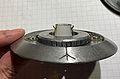
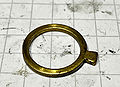
Dial ring.
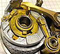
Friction rollers on both sides of the primary cam.


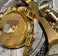
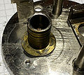
The dial ring can be seen on the bottom of the second picture, and it has a separate lead shield and a mechanism for adding friction to dialing. The part on the right is the closest to the container and has a lead shield in it.
In the middle of the dial ring is a part that increases dial friction by pressing the plastic tube onto the spindle. Around it the lead shield.
So the dial itself already adds friction to make getting readings out of the lock harder, but in addition to that the lock mechanism itself has two friction rollers that are pressed into the primary cam by springs. They only touch the primary cam. They add both friction and noise.
Disassembly
Disassembling the Mark IV is fairly easy, although you'll likely want circlip pliers to get some retainer clips off the wheelpost. Other than that you'll be good with a flathead screwdriver to get the lever screw off, and a small (size 4-ish) flathead for removing a friction roller and maybe helping with getting springs off / back on.
The following photos give a 360° view of the insides after the cover has been removed.
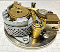
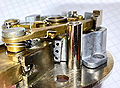
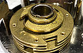
Right hand view.
Vertical up view.
Left hand view.
Vertical down view.


Right hand view showing part of the shielding and the other friction roller. Note how the spring is attached so you can get it back on.
Vertical up view, showing lever and cam gate, shielding, and the other friction roller. Note the spring and the screw on the roller.
Left hand view, showing bolt, lever screw, lever spring, lever, part of the wheel pack and more shielding. Note lever spring position.
Vertical down view, showing friction roller, bolt, lever screw and lever. Roller spring position can be seen again.
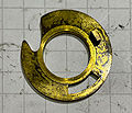
Primary cam removed.
Underside of primary cam.
Lever, spring, and screw.
Lever with screw.


Remove the primary cam. Underneath you'll find the first retainer clip for the secondary cam, the secondary cam fly and washers under it. This particular lock had 2 washers under the fly but this is apparently not common. Secondary cam gate is at the nose.
The primary cam's underside has a drive pin as usual, this time it just doesn't drive the wheels directly but the secondary cam underneath it.
Now you can remove the lever and bolt by unscrewing the lever screw (careful with the spring) and then pulling the bolt out


Next step is to remove the friction rollers.
The bigger one pops off with just a pull, but again be careful with the spring.
The small roller requires a screwdriver and a bit more care with the spring.
Shielding.

Once the lever, bolt and rollers are off you can then remove the shielding. It takes a bit of angling to get it to come off.
Secondary cam and wheel pack.
Retainer clip and fly on wheel pack.
Retainer clip, fly, washer.
Underside of secondary cam, showing drive pin that actually drives the wheel pack.
Wheel pack with cams removed.
Closeup of wheel fly. Flat unlike the cam fly.


Only the secondary cam and wheelpack are now left.
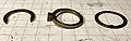
Closeup of retainer clip, fly, and the washers under the fly (might just be one washer in your case.) Getting under the side of the clip via the notch in the wheel post is also possible with a thin hook tool, but I just used circlip pliers.
Once you get the retainer clip off, these are the parts you'll see in order from left to right. Note that the fly's "nose" points down.
Now you can remove the secondary cam. Under the secondary cam there is another retainer clip and then the 3rd wheel's fly and its washer.
Now you just remove wheels in order. Remember which one is the 3rd wheel so you can get it back in the right position when reassembling. Under each wheel you'll find a washer, a fly and another washer.
The "top" side of a wheel with place for fly at around 9 – 11 o'clock in the center.
Bottom of a wheel with drive pin at around 12 o'clock in the center.
Remember that the bottom wheel, ie. wheel 1, doesn't have a drive pin since it's got nothing to drive.
Tension washer.


Under the 1st wheel you'll find a tension washer that is used to adjust how much torque you need for the wheels to turn. Extremely simple, just a bent washer that you bend more if you need a stiffer wheel pack and straighten out if you need it looser.
And that's it, your lock is now fully disassembled. Reassembly is obviously the same but in reverse order.